Blast Mitigation Information
 Click here to view our Blast-Resistant Windows and Doors brochure.
About Blast Mitigation
While total protection from bomb blasts and explosions is not possible, there are steps we can take to mitigate the extent or even likelihood of damage. In the more obvious situations, Blast-resistant windows and doors have long been used; and an increase in blast-type attacks or events has created a need for higher levels of protection in a wider range of applications.
Why Use Blast Windows and Entry Systems?
Since the 1995 bombing of the Oklahoma Federal Building, the incorporation of blast-resistant windows for high-profile buildings has become a standard practice. Whether for retrofit or new design, blast-resistant windows and doors are a design “fact of life” today. As hard-won experience and research teaches us more about the wide-ranging effects of explosions on buildings, it’s clear that blast and ballistic resistant windows and doors will benefit a broad range of structure types (and especially their occupants) in addition to high-profile buildings.
In response to the 9/11 terrorist attacks, Graham Architectural Products began making blast-resistant products and supplying them to government and private customers. Our engineering department has extensive knowledge of government specifications and application processes that ensure proper design for the intended purpose. We are committed to an active testing program for all these products in compliance with all applicable standards.
There is no such thing as blast proof.
You often see or hear terms like: “blast proof”, “bullet proof”, “fire proof”, “water proof”. What do they really mean? In the case of “blast proof” it would mean that the window would have to withstand anything from a stick of dynamite to an a truck bomb! Windows and doors are built to withstand certain threat levels, to withstand pressures/impulses that model the effects of an explosion. If a window or door was truly “blast proof” you would not be able to see through it due to the thickness of the glazing used. It would be hard or impossible to install due to the required materials assembled weight, or the building structure itself might fail to support such a weight. A window that survives a huge explosion is of little use in a building that doesn’t!
Blast Hazard Definitions
|
Blast Pressure – It only takes 15 PSI to rupture eardrums and cause lung damage. Depending on the blast load and distance from target, the pressures created during an explosion can be extreme. Secondary Fragments – such as shrapnel, rocks, and dirt can be propelled at very high speeds and travel large distances. You cannot always protect completely against these secondary fragments. Structural Collapse/Damage – This is the most devastating and deadly. Structural collapse occurs when a pressure load is stronger than the actual building components themselves, causing building structure failure. |
 Primary Fragments – are the most obvious hazard which consists of flying glass pieces and shards that can travel at speeds of 100 ft/second (68 mph) to excess of 200 ft/second (136 mph).
Anti-Terrorism Force Protection (ATFP)
Due to recent events, Anti-Terrorism Force Protection (ATFP), commonly known as blast protection, has increasingly become an area of focus in building/structure design. Beginning with the terror bombing of the World Trade Center in 1993 and continuing through the 1995 attack on the Murrah Federal Building in Oklahoma City, the Khobar Towers bombing in 1996, the U.S. Embassies bombings in Africa in 1998, and of course the September 11, 2001 attacks – not to mention hundreds of other terror bombings around the world from Bali to Britain – it’s clear that terror attack prevention and protection must be top national concerns.
Since 9/11 in particular, our awareness and perception of the effects of explosive attacks has been dramatically altered. A shocking statistic: according to Applied Research Associates (blast consultants), more than 8,000 actual bombings occurred between 1993 and 1997, injuring 2,750 and killing over 300 people in the United States!
The main targets for these attacks are government facilities. Given that well-placed explosives, whether delivered by personnel or by vehicle, are the favorite weapon of many terrorists, protecting buildings and their occupants from the effects of high-power blasts is a priority of the highest order.
Collateral Damage -Loss of Life, Business Disruption, Property Damage
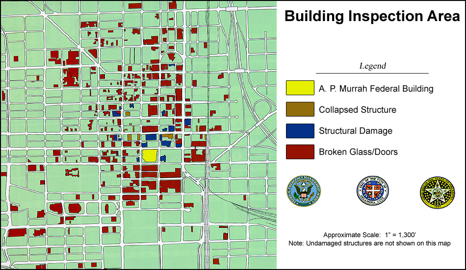
It should be noted that blast hazards are not limited to the particular building where the blast event occurs, but also the surrounding area, which is impacted to varying degrees as illustrated in this graphic that depicts damage from the Oklahoma City bombing. Buildings that were more than 10 blocks away from the A.P. Murrah Federal Building encountered broken glass and doors. Many buildings within a few blocks sustained structural damage and some even collapsed.
Within a city, the over-pressure waves created by an explosion cannot readily escape and dissipate. Near-by buildings channel pressure waves from the blast just like the walls of a garden hose channel water. In city streets, a portion of the pressure wave can dissipate upwards but much of it will move through the streets, reflecting and rebounding off buildings and pavement as it travels outwards from the origin of the blast.
Anatomy of a Blast Event
Charge Weight
-
- Amount of explosives used (TNT equivalent)
- Typically measured in pounds or kilograms of TNT
Stand-off Distance
-
- Distance from point of detonation to the target
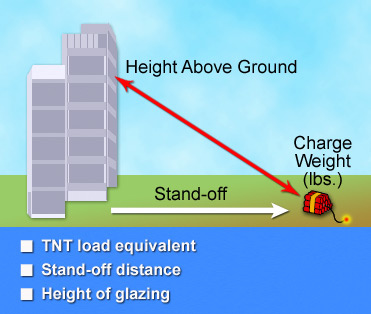
Figure 1
Buildings are designed to meet certain pressures which are generated from two quantitative points – charge weight and stand-off distance. The charge weight is the power of the blast, expressed as the equivalent weight of TNT that is considered to be the most likely the building will encounter. This threat may not necessarily be considered actual TNT and is dependent upon the type of threat and explosive being considered. This is an educated guess based on the local environment and conditions from a threat assessment. This method of estimation has its limitations, as a large enough blast will overcome virtually any preventive measures. In the 1995 Murrah federal building attack, for example, a truck bearing the equivalent of 5000 pounds of TNT detonated right next to the front door.
The stand-off distance is the distance between the building and the potential location for an explosive detonation. This is usually determined, at a minimum, by the “controlled perimeter,” meaning a physical boundary at which access by vehicles or individuals is controlled, such as by fencing, concrete barriers or other means.
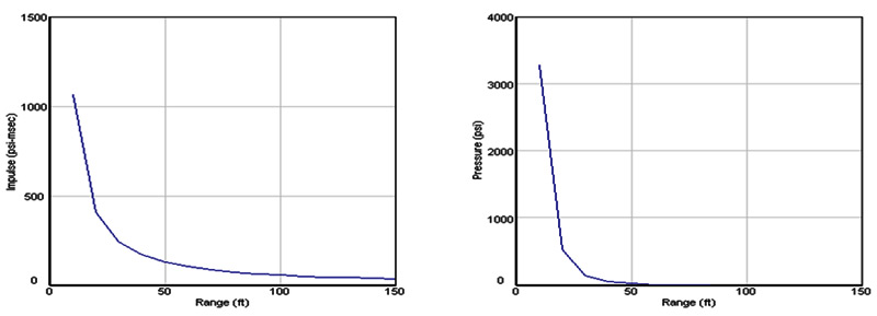
The greater the stand-off distance is, the lesser the explosive threat to the building. The constraints of a given project (building property footprint, etc.) can reduce the maintainable Stand-Off distance; this situation may be compensated for through other design considerations. The key concept is that the further away the blast charge is from the target building, the greater the drop in blast wave pressure. This pressure drops exponentially as stand-off distance increases.
Duration & Pressure
- Duration
- The time a blast pressure load is applied to the target
- 30-40 blast durations occur in 1 blink of the human eye
- Measured in mili-seconds (msec, thousandths of a second)
- Peak Pressure
- Occurs instantaneously
- Dissipates exponentially
- Maximum pressure during incident
- Over Pressure
- Pressure reading over atmospheric pressure
- Reflected Pressure
- Pressure wave that has rebounded off the target or surrounding structures
Peak & Over Pressure: Used interchangeably. It is just the maximum pressure generated by a detonation at the target or at the point of measurement of the pressure.
Air blast pressures occur very quickly and are typically measured in milliseconds. Please keep in mind that results vary for differing structural materials. Flexible materials will absorb the energy and rigid materials essentially resist the energy. Both are valid design approaches. Material strength will be affected by the choice of a flexible or ductile material.
Shock Wave
- Positive Phase of Pressure
- Time the pressure acts positively on an object
- Impulse (very important)
- Area under pressure-time curve
- Measure of the total energy acting on an object
- Impulse= ½(t x d)
- t = duration & d = pressure
- Negative Phase of Pressure
- Rush of air to fill the void behind the blast wave
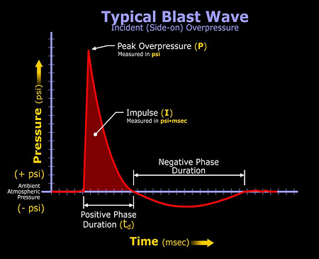
Figure 2
Positive pressure is the pressure that is produced by a blast in a positive movement.
Negative pressure is when the positive pressure wave passes and the air is trying to fill the void left behind, i.e., rushes back in. It is possible for windows to be sucked out of their test fixtures rather than blown into the protected area during blast testing.
The peak pressure of the blast and the time over which the initial pressure wave decays to zero together define the impulse energy delivered. While pressure is instantaneous, the delivered energy is cumulative, and is at the root of the damage that can result. Mathematically, the impulse energy is figured as the area under the pressure-time waveform.
Although blast loads are applied very quickly – within milliseconds – their characteristics exhibit a distinctive profile. As this graph shows, the typical waveform features a positive phase as the blast pressure acts from the exterior, characterized by a virtually instantaneous rise to the peak overpressure. There is then a rapid decay of pressure to zero.
After the pressure wave expands the air in the blast wave, creating a vacuum, air will rush back in to fill it. This causes the negative pressure phase. Finally, there is a rebound phase as pressures equalize.
The impulse as displayed on the curve in Figure 2 is the area under the positive overpressure blast curve. It is a function of pressure and time and is mathematically calculate by ½ x pressure x duration. This is the formula of area of a triangle ½ x base x height. It is essentially a triangle.
Designing Blast-Resistant Structures
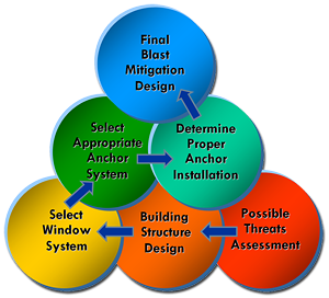
Once the blast threat has been determined, a systems approach to mitigating that threat is recommended. Using the combined criteria of the threat assessment, the available building preparation and a desired window system, the designer can develop a comprehensive blast mitigation design solution.
There are different types of blast threats; designs can be created for other explosives or combustibles as well as for TNT. For example in an oil refinery, the threat may be oil or gas explosions but for blast the threat has to be converted to equivalent TNT quantity in order to calculate the blast pressure and impulse.
The building structure walls and supports need to be analyzed for blast resistance. The structure must support the blast load as well as the components within the facade.
The selected windows must be of the proper operation type with an appropriate anchor system and installation detail. The anchors have to be analyzed and stresses calculated to withstand the projected load. Size and spacing as well as brand of anchor to use for the designed conditions are given on approved drawings. Typically these are heavy duty engineered anchors. Window installation should be done by contractors experienced with blast window and door installation. There is no magic to the installation process; blast mitigation projects employ heavier duty units; thicker glass, larger and more anchors, and heavier frames.
Building Preparation and Design
- A building cannot be designed to be blast or ballistic proof. The key is to limit the damage to an acceptable level.
- An important consideration is how extensive and how widespread is the localized or “acceptable” damage?
- Good design is always a compromise between acceptable damage and product cost.
- Products can be designed to reflect (rigid) or absorb (flexible) energy.
Unknown factors make it impractical to attempt to prevent damage under all circumstances. Rather, the design objective is to mitigate the effects of a blast – that is, to diminish the severity of damage and reduce the potential for injury and death.
For some buildings, blast resistance may not be possible/practical. In some situations the problem can be a trade-off between functionality and security; in other situations it may be costs.
Determining what damage is acceptable can be a hard question to answer when dealing with human life and property assets.
- Information Required for design calculations:
- Charge weight & Stand-Off
- Charge weight: lbs of TNT
- Stand-off: feet or meters
- Pressure & Duration
- Pressure: PSI or kPa (kilopascal)
- 1PSI = 1/7 x kpa
- Duration: msec
- Pressure: PSI or kPa (kilopascal)
- Pressure & impulse
- Pressure: PSI or kPa (kilopascal)
- Impulse: PSI-msec
- Charge weight & Stand-Off
Charge Weight and Stand-off
- How Charge Weight & Stand-off Relate
- As charge weight increases, peak pressure increases
- Pressure decreases exponentially with stand-off distance
- As stand-off distance increases, peak pressure decreases, and duration changes (greater impulses)
- Both are used to determine Peak Overload, Pressure and Impulse
Buildings are designed to meet certain pressures and impulses which are generated from two quantitative points – charge weight and stand-off distance (previously discussed in detail).
Pressure and Distance
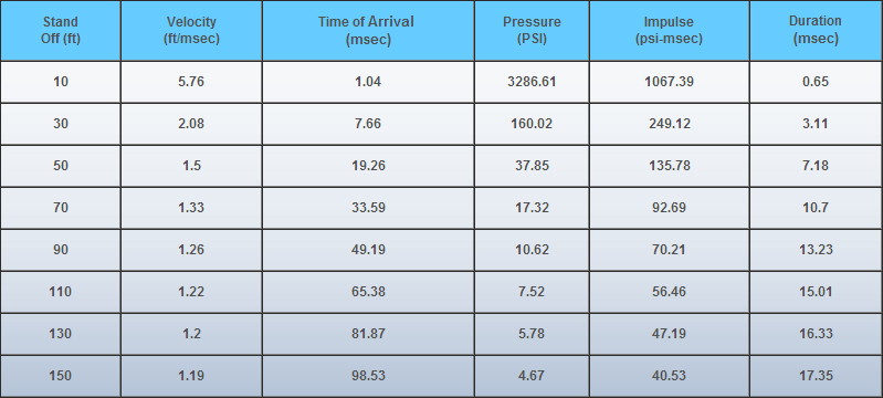
Analytical methods are used to determine or predict the blast effect of various threat levels on a building. Analytical methods exist in the form of several government sponsored software products available to designers, including WINGARD, WINLAC, HAZL, ATBLAST and SBEDS.
- WINGARD, which stands for Window Glazing Analysis Response and Design, is available for download at www.oca.gsa.gov (Only with approval from SSA).
- WINLAC is short for Window Lite Analysis Code and is controlled by the U.S. Department of State. It is distributed to only a few cleared contractors and selected government representatives.
- HAZL stands for window fragment Hazard Level Analysis and is also a controlled item. Security contractors must provide the name of their sponsoring government agency and its contact information. The U.S. Government Printing Office (GPO) should be contacted for more information.
- ATBLAST is a software program that estimates the blast loads that develop during an open-air explosion and is a proprietary computer program developed by Applied Research Associates. It is provided at no cost to the government and to authorized users.
- SBEDS is an Excel© based tool for the design and analysis of structural components subjected to dynamic loads, such as air blast from explosives, using single-degree-of-freedom (SDOF) methodology. SBEDS is based on Army TM 5-1300 (also designated as NAVFAC P-397 and AFR 88-22) and UFC 3-340-01, but draws on other sources where improved methodologies are available. It is available from the US Army Corp of Engineers Protective Design Center.
Glazing options
Include laminated glass, window films or polycarbonate. Insulating glass units are also an option under specific conditions.
Laminated Glass
-
Laminated glass is available with many different inner-layers and configurations
- Laminated/Air Space/Laminated
- Best, but typically cost prohibitive
- Annealed or Tempered/Air Space/Laminated
- More cost effective
- Laminated/Air Space/Laminated
Translated into product characteristics, the Department of Defense (DOD) recommends the following:
For glazing, use laminated glass. The DOD recommends a minimum ¼-inch laminated glass with a 0.030-inch interlayer. This varies with the level of protection sought, the postulated charge weight and the Stand-Off distance.
ASTM F 2248-03, Standard Practice For Specifying An Equivalent 3-second Duration Design Loading For Blast Resistant Glazing Fabricated With Laminated Glass, offers guidance in the selection of laminated glass. It works with ASTM E 1300 to help specifiers select the thickness and type of blast-resistant laminated glass for fenestration glazing.
Note that when specifying laminated glass, some specifiers mistakenly use polyvinyl-butyral – or PVB – and “interlayer” interchangeably. However, there are more types of interlayers than those made with PVB – such as plasticized PVB, aliphatic polyurethane sheet, cured resin and others. Don’t limit your choices.
With lami (laminated) glass not only can you have blast resistance but it can also be bullet resistant, hurricane impact resistant, forced entry rated, and more. It all depends on the combination of laminated glass, polycarbonates, acrylics, and the interlayer’s that are used. These products must also be tested in order to be able to combine different security ratings together.
Window Films
- Typically used for retrofit applications.
- Film is applied to inside of glass
- Quick fix for U.S. Embassies after 9/11
- Unknown life span
- Possible UV caused ‘yellowing’
- Glass may disengage from frame if not mechanically fastened
- Windows may disengage from building
|
Films can also be applied to windows to retain glass fragments in the event of a blast. Films were very popular in government buildings immediately following September 11th. The life span of these films is unknown due to the effects of time, cleaning agents and exposure to scratching and tearing. The damage caused by these factors will vary with the specific film selected. These films may also “yellow” due to UV exposure. The 2007 revision to the UFC will not allow the use of films on any military windows or doors in a DoD building. Polycarbonate Polycarbonate is very flexible and requires large glazing bites. Due to this flexibility, not only will the lites be extraordinarily thick, but the entire polycarbonate lite may disengage under a blast load. This product is very strong. It is considered 250 times stronger than glass and is great for ballistics, forced entry and high level blast applications. |
|
|
Insulating Glass (IG)
|
|
An advantage with the IG units is greatly increased energy efficiency.
Anchor and Trim System
- Must be able to resist blast loading
- Must be evaluated for type, size, spacing and embedment
- Must maintain edge clearances
- Must attach to building structural substrates and transfer the load
- Failure can mitigate effective blast resistant windows
- Engineering review recommended
Anchors must be used that can resist specified equivalent static loads, which vary with the vision area. The connection design load can also be determined per ASTM F 2248.
Designers must calculate bending, shear, bearing and pull-out loads for the connectors, taking the size and geometry of the particular frame and connector configuration into account.
Many types of anchor designs can provide the required blast resistant attachment for the project. Selection of the proper anchor depends on the applied load, the framing material, the thickness of the frame at the anchor, the gap between the frame and the wall, the number and spacing of the anchors, and the wall material and construction. Review by a professional engineer is recommended when designing anchorage for blast mitigation.
Installation
- Install products in strict accordance with approved shop drawings
- Installation can be reviewed/certified by an independent person/agency
- Consider hiring trained and experienced installers
The project architect or specifier must consider installation details, as this can easily become the weakest link. Insist on precise construction documents, including using type, size, spacing and embedment per blast loads and engineering review. Allow for proper edge clearance; and use epoxy where required.
The architect or specifier should also ensure that the installation of blast products is in strict accordance with approved shop drawings. Training programs are offered to familiarize installers with requirements. Alternately, the installer’s experience with the specific type of application should be considered. An experienced installer trained specifically for the installation of blast resistant fenestration products is recommended.
Finally, a very thorough commissioning and final inspection process should be performed.
Test Methods
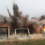
Open Arena
- Detonation of an actual explosive devise is required
- Cannot be safely done on a project site
- Should always be performed by an experienced blast engineering firm

Shock Tube
- High pressure air pulses are released through a pipe or tube directed at the test specimen
- Can be performed safely in a controlled accredited laboratory setting
As with most material performance requirements, blast mitigation employs both laboratory and field testing as a means to quantify actual performance. For blast resistance, these test methods have developed over time from several sources. Both deal, in one way or another, with one or more of the two basic approaches to testing windows for blast resistance. These are open arena and shock tube testing. The open arena method allows for testing of multiple windows at one time, while the shock tube method allows only one window test at a time. Both methods require three samples to pass in order for a product to be considered as “passing” or acceptable.
Detailed instructions for the conduct of these test methods have been documented in the form of GSA and ASTM standards.
GSA-TS01-2003, Standard Test Method For Glazing And Glazing Systems Subject To Dynamic Overpressure Loadings, recognizes both open arena testing and simulated blasts utilizing the shock tube method.
ASTM F 1642 -04, Standard Test Method for Glazing And Window Systems Subject to Airblast Loadings, also describes both open arena and shock tube test methods and sets forth six hazard ratings for glass breakage. These ratings are similar, but do not directly correspond to, the blast rating tables in GSA-TS01-2003 and UFC 4-010-01.
The arena test, as the name implies, is an open-field test that most accurately reproduces the blast waveform by employing an actual explosion; however it is the most costly option. Because peak pressure declines with distance from the blast, but the delivered impulse energy actually increases, a good arena test set-up must be quite large with long Stand-Off distances.
The shock tube test is a method that uses an air cannon powered by high pressure air or nitrogen. It provides a much better simulation of the positive phase of the blast waveform, and at low cost, but still does not address negative and rebound phases of the blast wave.
Inspired by the growing number of bomb attacks, several government and industry groups have documented blast mitigation methodologies that have developed over the past decade.
These include test methods, standards and guidelines developed by the General Services Administration (GSA), the Department of Defense (DOD) the American Society For Testing And Materials (ASTM), and the American Architectural Manufacturers Association (AAMA), among others.
Current Guideline Specifications
- ASTM F 1642, Standard Test Method for Glazing and Glazing Systems Subject to Airblast Loadings
- GSA-TS01-2003, Standard Test Method for Glazing and Window Systems Subject to Dynamic Overpressure Loadings
- UFC 4-010-01, Minimum Antiterrorism Standards for Buildings
- ASTM E 1300, Standard Practice for Determining Load Resistance of Glass in Buildings
- ASTM F 2248, Standard Practice for Specifying an Equivalent 3-Second Duration Design Loading for Blast Resistant Glazing Fabricated with Laminated Glass
- AAMA 510-06, Voluntary Guide Specification for Blast Hazard Mitigation for Fenestration Systems
The General Services Administration (GSA) & American Society for Testing and Materials (ASTM) both have testing methods and rating levels for fenestration products and glazing subjected to blast loads. The information below summarizes each and compares them side by side.
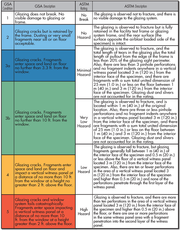
GSA/ISC Hazard Classification
The GSA Criteria define five injury hazard performance conditions to indicate whether and how far glass shards penetrate into a room when the window and wall segment are subjected to a blast of calculated impact pressure. The protection performance conditions are numerically defined from 1 (“safe”) through 5 (“low protection”).
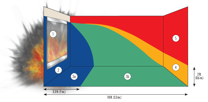
The chart shows injury hazard classifications 1 through 5, per GSA/ISC.